Introduction
The HVAC CFM Calculator is a vital tool for determining the heat loss and required air flow rate for heating a room. By inputting the areas of windows/doors, walls, ceiling, and floor, along with their insulation types and temperatures, the calculator computes the total heat loss (in BTU/hr and kW) and the air flow rate needed (in m³/s, m³/h, and L/s) to maintain a desired room temperature, ensuring efficient HVAC system design.
Why is the “HVAC CFM Calculator” Important?
Accurate heat loss and air flow calculations are essential for:
- Efficiency: Sizing HVAC systems correctly to avoid energy waste or insufficient heating.
- Comfort: Maintaining consistent indoor temperatures for occupant comfort.
- Cost Savings: Optimizing system design to reduce installation and operational costs.
- Compliance: Meeting building codes and energy efficiency standards for residential and commercial spaces.
How the “HVAC CFM Calculator” Works
The calculator processes user inputs—areas of room components, their insulation types, and temperatures—to compute heat loss and air flow rate. It multiplies each component’s area by its heat multiplier (H*M) to calculate heat loss in BTU/hr, converts to kW, and uses the temperature difference, specific heat, and air density to determine the air flow rate. Results are displayed in multiple units for versatility.
Formulas Used in the “HVAC CFM Calculator”
The calculator relies on the following equations:
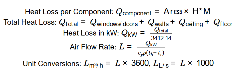
- Heat Loss per Component: \( Q_{\text{component}} = \text{Area} \times \text{H*M} \)
- Total Heat Loss: \( Q_{\text{total}} = Q_{\text{windows/doors}} + Q_{\text{walls}} + Q_{\text{ceiling}} + Q_{\text{floor}} \)
- Heat Loss in kW: \( Q_{\text{kW}} = \frac{Q_{\text{total}}}{3412.14} \)
- Air Flow Rate: \( L = \frac{Q_{\text{kW}}}{c_p \rho (t_h - t_r)} \)
- Unit Conversions: \( L_{\text{m}^3/\text{h}} = L \times 3600 \), \( L_{\text{L/s}} = L \times 1000 \)
4.1. Where:
- \( \text{Area} \): Surface area of each component (ft²).
- \( \text{H*M} \): Heat multiplier for each component (BTU/hr-ft²).
- \( Q_{\text{total}} \): Total heat loss (BTU/hr).
- \( Q_{\text{kW}} \): Total heat loss (kW).
- \( c_p \): Specific heat of air (1.005 kJ/(kg°C)).
- \( \rho \): Density of air (1.2 kg/m³).
- \( t_h \): Heating air temperature (°C).
- \( t_r \): Room temperature (°C).
- \( L \): Air flow rate (m³/s).
Step-by-Step Breakdown of the Formulas
The calculation process involves:
- Input Areas and Types: Enter the areas (ft²) for windows/doors, walls, ceiling, and floor, and select their insulation types.
- Input Temperatures: Provide the heating air temperature (\( t_h \)) and room temperature (\( t_r \)) in °C, °F, or K.
- Assign H*M Values: Map each component type to its heat multiplier (e.g., Single Insulated windows = 41 BTU/hr-ft²).
- Calculate Component Heat Loss: Multiply each area by its H*M to get heat loss in BTU/hr.
- Sum Heat Loss: Add the heat losses to get total heat loss in BTU/hr.
- Convert to kW: Divide total heat loss by 3412.14 to convert to kW.
- Convert Temperatures: Convert \( t_h \) and \( t_r \) to °C if needed.
- Calculate Air Flow Rate: Use \( L = \frac{Q_{\text{kW}}}{c_p \rho (t_h - t_r)} \) to compute air flow in m³/s.
- Convert Units: Convert air flow to m³/h (\( \times 3600 \)) and L/s (\( \times 1000 \)).
- Format Results: Display heat loss with 2 decimal places (BTU/hr) or 4 decimal places (kW), and air flow with 4 (m³/s) or 2 (m³/h, L/s) decimal places, using scientific notation for values less than 0.001.
Example Calculation
6.1. Input Values
- Windows/Doors Area: 100 ft², Single Insulated
- Walls Area: 300 ft², 2 inch insulation
- Ceiling Area: 100 ft², 6 inches insulation
- Floor Area: 100 ft², Overhang 3 inch
- Heating Temperature (\( t_h \)): 40°C
- Room Temperature (\( t_r \)): 20°C
6.2. Calculation Steps
- Windows/Doors Heat Loss: \( 100 \times 41 = 4100 \, \text{BTU/hr} \)
- Walls Heat Loss: \( 300 \times 6 = 1800 \, \text{BTU/hr} \)
- Ceiling Heat Loss: \( 100 \times 4 = 400 \, \text{BTU/hr} \)
- Floor Heat Loss: \( 100 \times 5 = 500 \, \text{BTU/hr} \)
- Total Heat Loss: \( 4100 + 1800 + 400 + 500 = 6800 \, \text{BTU/hr} \)
- Heat Loss in kW: \( \frac{6800}{3412.14} \approx 1.9932 \, \text{kW} \)
- Air Flow Rate: \( L = \frac{1.9932}{1.005 \times 1.2 \times (40 - 20)} \approx 0.0826 \, \text{m}^3/\text{s} \)
- Air Flow in m³/h: \( 0.0826 \times 3600 \approx 297.36 \, \text{m}^3/\text{h} \)
- Air Flow in L/s: \( 0.0826 \times 1000 \approx 82.60 \, \text{L}/\text{s} \)
- Results: Total Heat Loss = 6800.00 BTU/hr, 1.9932 kW; Air Flow Rate = 0.0826 m³/s, 297.36 m³/h, 82.60 L/s
Conclusion
The HVAC CFM Calculator streamlines the process of designing efficient heating systems by accurately calculating heat loss and air flow requirements. It supports various room configurations and insulation types, making it an essential tool for achieving comfort, efficiency, and compliance in HVAC system design.
How to Use the “HVAC CFM Calculator”
8.1. Understanding the Input Fields
- Windows & Doors Area: Enter the total area (ft²) and select the type (e.g., Single Insulated).
- Walls Area: Enter the area (ft²) and select insulation level (e.g., 2 inch).
- Ceiling Area: Enter the area (ft²) and select insulation thickness (e.g., 6 inches).
- Floor Area: Enter the area (ft²) and select type (e.g., Overhang 3 inch).
- Final Temp (\( t_h \)): Enter the heating air temperature and select unit (°C, °F, or K).
- Room Temp (\( t_r \)): Enter the desired room temperature and select unit (°C, °F, or K).
8.2. How to Interpret the Results
- Total Heat Loss (BTU/hr): Total heat lost through all components (BTU/hr).
- Total Heat Loss (kW): Heat loss converted to kilowatts.
- Air Flow Rate (m³/s): Volume of air needed per second to offset heat loss.
- Air Flow Rate (m³/h): Air flow in cubic meters per hour.
- Air Flow Rate (L/s): Air flow in liters per second.
Practical Applications & Expert Insights
9.1. Where the “HVAC CFM Calculator” is Used
- Residential HVAC Design: Sizing heating systems for homes based on room insulation and climate.
- Commercial Buildings: Calculating air flow for offices, schools, or hospitals to meet comfort standards.
- Energy Audits: Assessing heat loss to recommend insulation or HVAC upgrades.
- Industrial Facilities: Designing ventilation systems for warehouses or factories with large surface areas.
9.2. Real-Life Scenarios
- Home Renovation: A homeowner uses the calculator to size a new HVAC system for a poorly insulated room, ensuring adequate heating.
- Office Retrofit: An engineer calculates air flow for an office with large single-pane windows to upgrade the heating system.
- School Upgrade: A facility manager determines heat loss in a classroom to comply with energy efficiency regulations.
9.3. Expert Recommendations
- Insulation Upgrades: Use higher insulation levels (e.g., 6-inch walls, 10-inch ceilings) to reduce heat loss significantly.
- Temperature Selection: Set \( t_h \) at least 10°C above \( t_r \) for efficient heating without excessive air flow.
- Accurate Measurements: Measure component areas precisely, as small errors can lead to significant miscalculations in heat loss.
- Consider Infiltration: This calculator excludes air infiltration; for precise designs, add infiltration losses separately using ASHRAE standards.
Frequently Asked Questions (FAQs)
10.1. What is the HVAC CFM Calculator?
It’s a tool that calculates the heat loss and required air flow rate for heating a room based on component areas, insulation types, and temperature differences, aiding in HVAC system design.
10.2. How is heat loss determined?
Heat loss is calculated by multiplying the area of each component (windows/doors, walls, ceiling, floor) by its heat multiplier (H*M) and summing the results in BTU/hr, then converting to kW.
10.3. Why must the heating temperature be higher than the room temperature?
The heating air must be warmer than the room to transfer heat effectively. If \( t_h \leq t_r \), no heating occurs, and the air flow calculation is invalid.
10.4. Can the calculator account for air infiltration?
No, this calculator focuses on conductive heat loss through surfaces. Air infiltration requires separate calculations based on air changes per hour (ACH) and room volume.
10.5. What are the practical applications of HVAC CFM calculations?
They are used in designing HVAC systems for homes, offices, schools, and industrial spaces, ensuring efficient heating, comfort, and compliance with energy standards.
10.6. Where can I find more information on HVAC design?
Refer to ASHRAE standards (www.ashrae.org), local building codes, or consult HVAC engineers for detailed guidelines on system design and heat loss calculations.
 Home
Home
 Back
Back